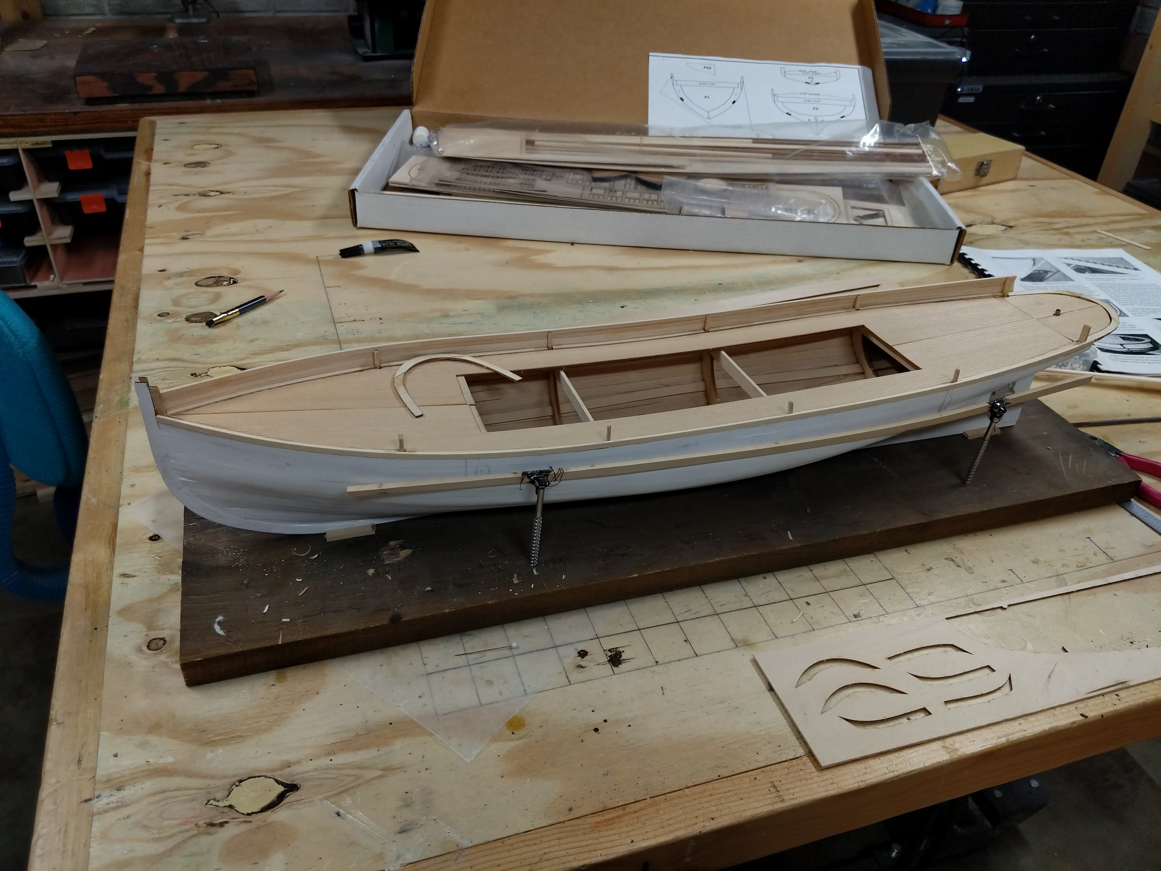
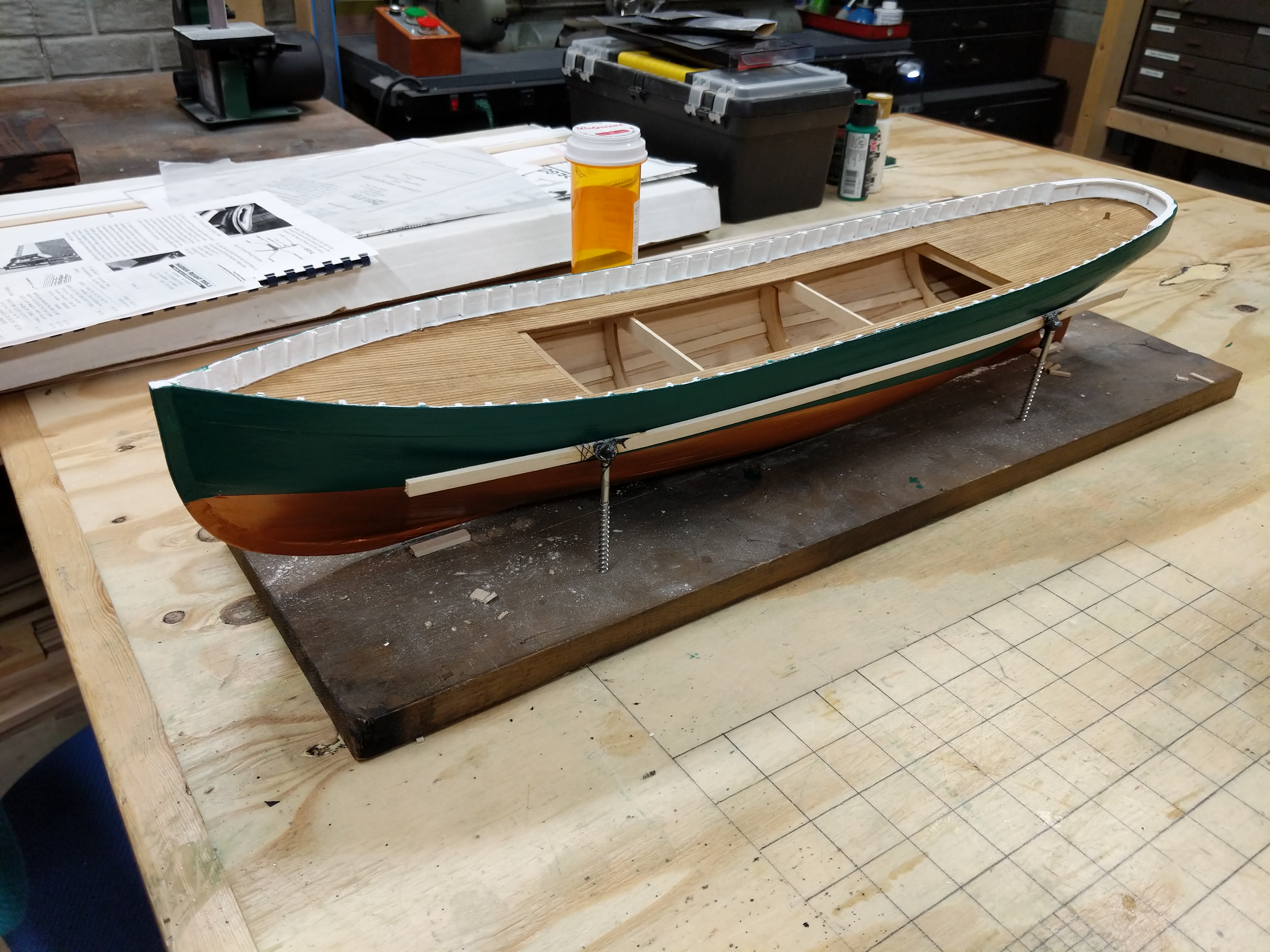
Every retired guy has a ship model or two, right? Usually in the box. I decided to get back to working on mine. I left off here about two years ago.
Actually this is after I did a little work on the side rails. It’s a model of a steam tug, the Sequin, from BlueJacket Ship Crafters in Belfast, Maine.
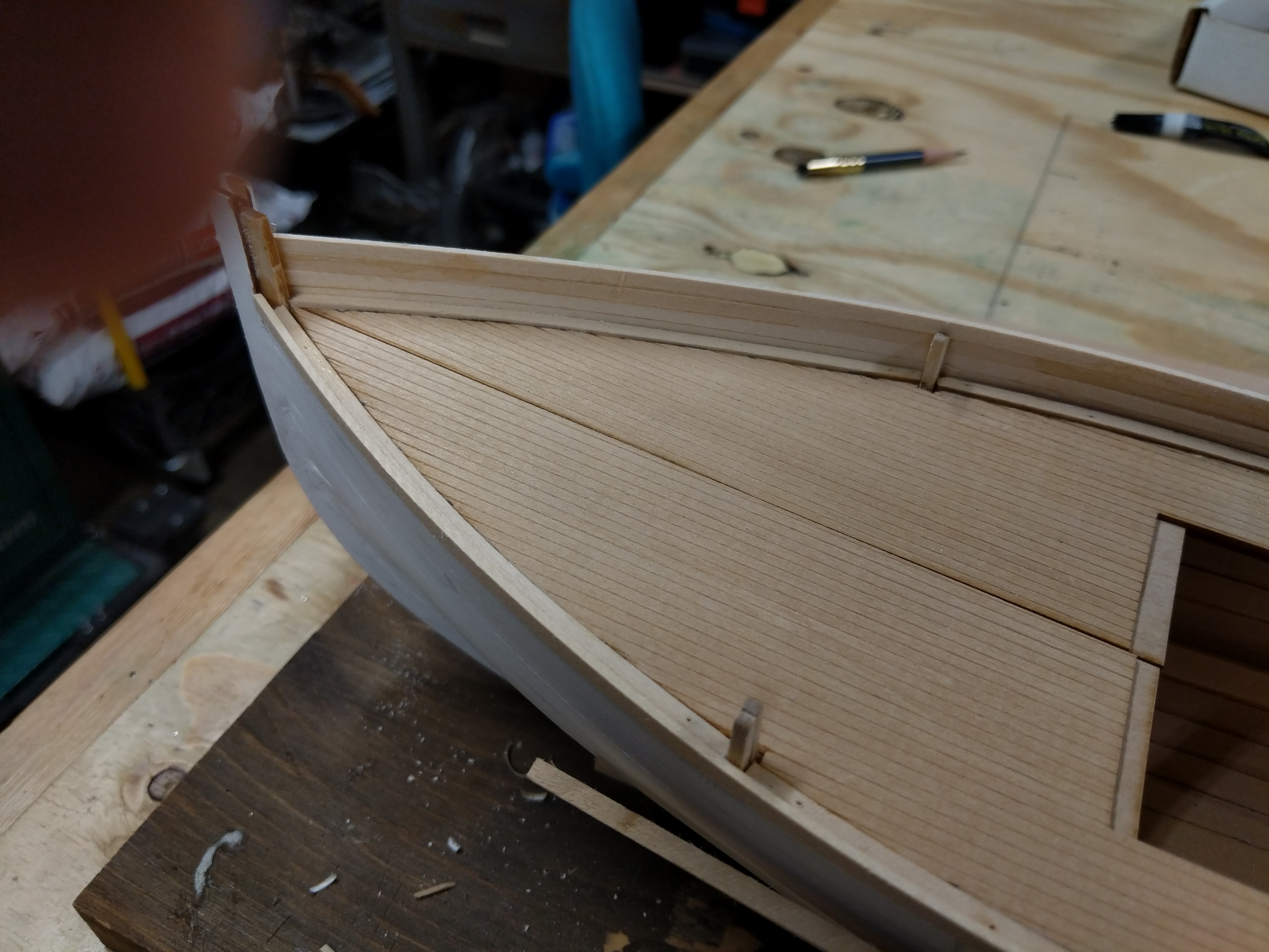
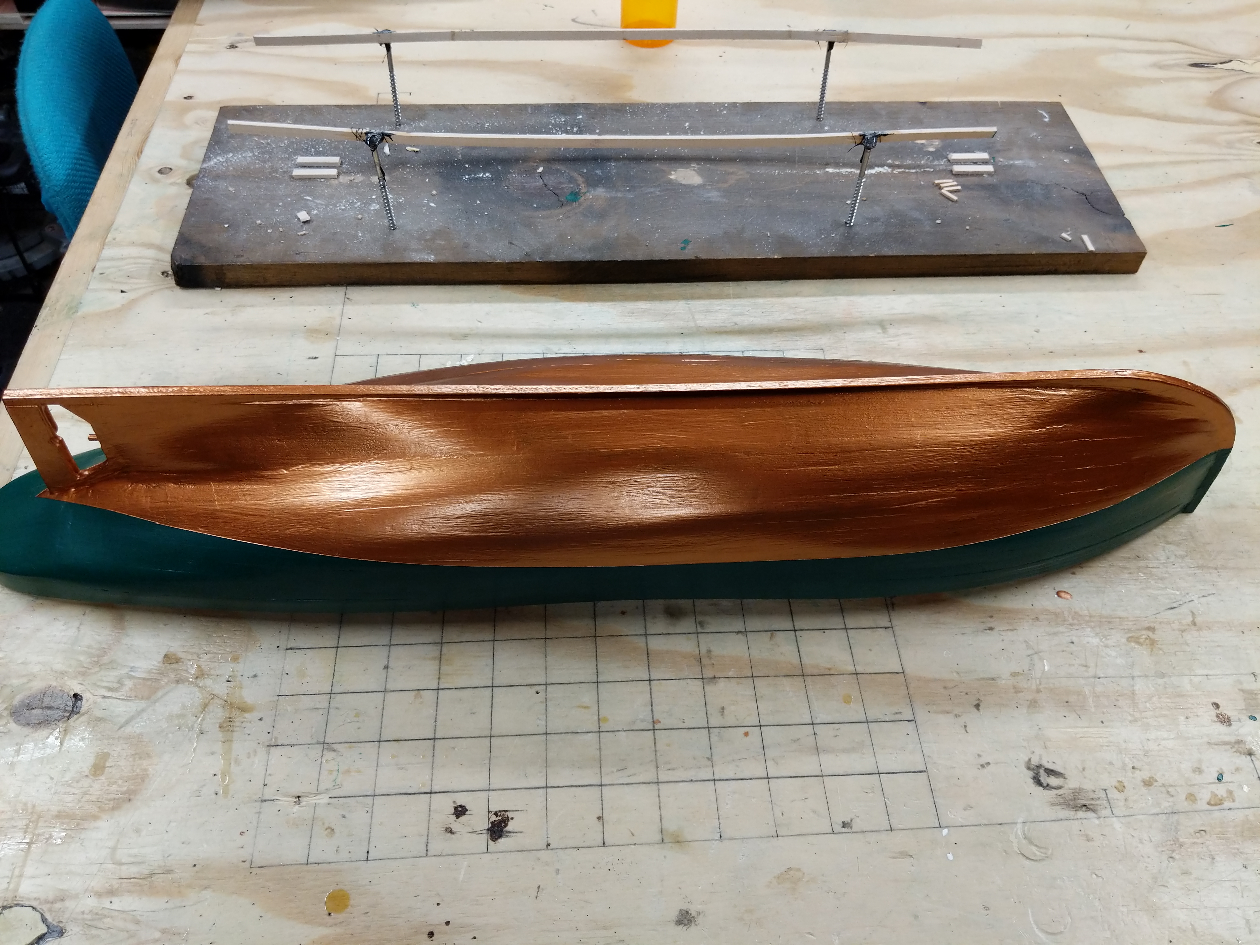
I finished the hull and did some of the painting. I particularly enjoyed cutting and gluing the eighty tiny frame-heads from 3/32 stock
Next task is to complete the mahogany railings and then I get to start on the superstructure.
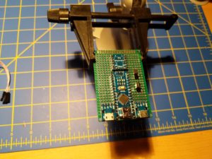
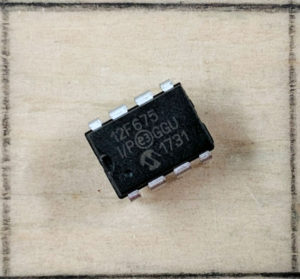
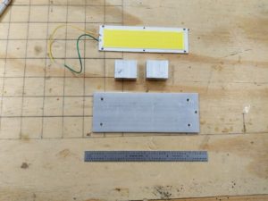
A while back Big Clive published a video about controlling a string of LEDs with a PIC 8 pin microcontroller. I lost track of the video but I remembered the concept and thought I’d give it a try. It’s based on the fact the LEDs are diodes that conduct in one direction only, and that the GPIO pins on the chip are “tri-state” – think plus, minus and off. Given that you can control 6 LEDs with three wires, and 12 with four wires. The eight pin PICs have 5 input/output pins ( a sixth is input only) so we should be good to go. Here’s the chip, standard 8 pin DIP package.
8 pin micro in a one inch square
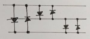
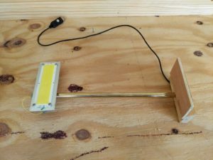
Let’s say we want the three wire version. We solder the LEDs in one direction – wire 1 to 2, 2 to 3, 1 to three, and then do the same in the opposite direction for a total of six. Then we program the micro to switch the wires – 1 plus, 2 minus, 3 off lights the LED that is wired anode to 1 cathode to 2 for example.
The pin states are not actually plus, minus and off. They are output logic high, output logic low, and input (high impedance). The output high = plus, and low = minus works fine, but high impedance on the input is not quite off, so you will get enough current leakage to light some LEDs that should be off unless you can choose your current limiting resistors just right.
Real programmers would write the code in assembler, but I chose to do it in C, just because I could. I used Matlab X and the PICkit 3 programmer. Getting the PICKit 3 to work is a drama that has been covered in many videos. Just plan to spend a few hours finding the secret sauce to make it all work. All you have to do is control two registers – TRISIO to define the state of the pins, and GPIO to switch them on and off when they are defined as output.
The heart of the code (for the three wire version seen in the cigar tube) looks like this:
In the four wire version I used an array rather than DEFINEs to enumerate the LEDs. This allows you to use loops and so forth for the sequences, but it eats a good part of the 64 bytes of data memory on the little chip.
for(int j=0;j<12;j++)
{
LedOn(j);
__delay_ms(DELAYTIME);
void LedOn(int i)
{
TRISIO = Led[i][1];
GPIO = Led[i][0];
}
Next maybe I'll move on to a 12F1840 with four times the program memory and a bunch of built in peripherals.
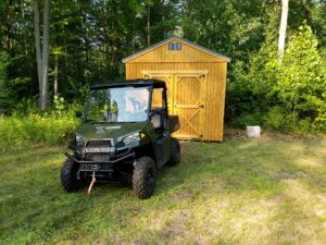
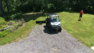
Now that we have a new utility vehicle it doesn’t quite fit in the garage the way the old one did. So we need a new home for Grizzly II.
A shed from Old Hickory Buildings is just the ticket. Watching it come up the 700 foot driveway was quite a treat.
Now we just need to get the green thing into the tan thing.
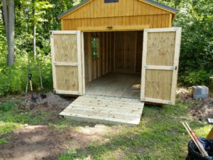
That involves building a ramp.
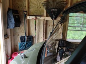
Then the real fun begins – outfitting the interior. It’s a bit far from the house so all the power for lighting and stuff will be solar. There is a “porch light” over the ramp, and a similar solar proximity light will be placed inside.
I built an LED lamp to light up the little workbench in the shed.
There is a “French Cleat” wall behind the workbench so that I can store stuff on any type of hanger or shelf I choose to invent.
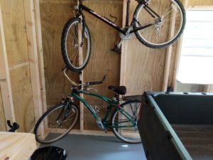
And of course, lot’s of wall space for everything else.
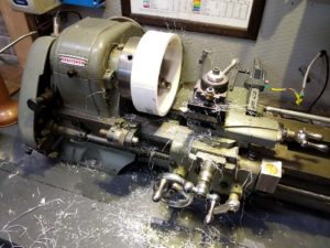
So, we take our sewer pipe elbow and cut ourselves a couple of rings.
Face them off in the lathe, drill mounting holes, paint, done.
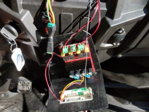
On to installation and electronics.
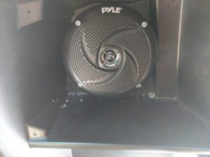
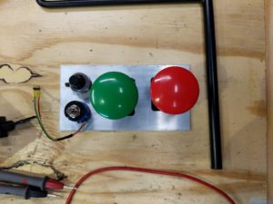
And a bit more machine work to make a volume knob (very important)
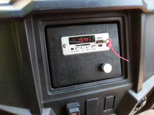
All done. I like the eleven dollar “12V/5V LED Car Bluetooth MP3 Decode Board Module Audio FM USB For HIFI Amplifier” (to quote the Chinglish) It really does all that stuff.
The panel is temporary – it will get changed out as we add even more gadgets. Next? GPS, lighting? We’ll see.
Grizzly, our original “snow plow” ORV that came with the house was nine years old, had no provenance, and was a Chinese brand no longer sold in the US. His latest problem was completely refusing to start. Provably repairable – that’s another story – but just the tip of the issue iceberg.
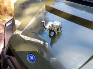
So we now have Grizzly 2. A Polaris Ranger 500 that only cost five times as much as my first car.
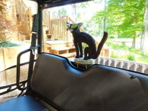
Naturally customization has begun. Howard’s elephant has been added. This hood ornament comes from Deb’s dad – Howard Eaton Clarke – who used it to adorn a number of on and off road vehicles.
And I’ve added the Halloween Cat that rode with me through the previous winter on Grizzly the First.
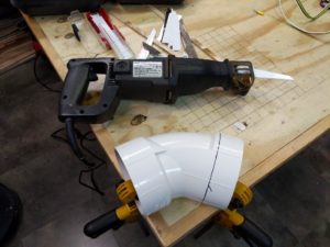
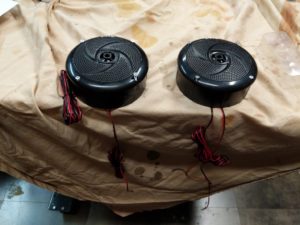
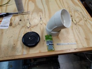
Next is the sound system. I bought a pair of “marine” speakers, and found the perfect place to mount them. Just cut a hole and pop them in, right? But wait, the other side of that hole was the front wheel well. They might be waterproof speakers, but I’m guessing a dose of four wheel drive propelled snow would not extend their service life.
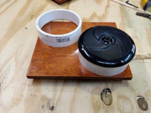
So the challenge is speaker mounts. Specifically, how to turn this 4 inch schedule 40 elbow into a pair of rings to mount the speakers.
Why this elbow? It was the cheapest part in the bin. Progress report in the next post.
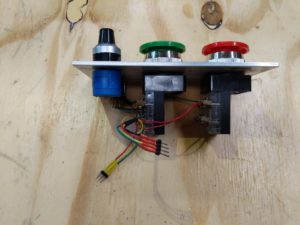
The control for the VFD (Variable Frequency Drive) on my lathe was pretty shoddy, so I decided to build a new one. I got a 3 X 6 inch piece of 1/8 thick aluminum sheet from Hobby Metal Kits, and drilled and bored the holes for the switches and the potentiometer.
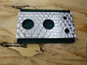
The really cool part was that I found out how to create the “brushed aluminum” finish on the panel. w
Glue a bit of Scotch Brite to a stick, put it in the drill press, and spin the pattern onto the aluminum sheet. I thought alignment would be tricky, but if you just slightly overlap the circles and then offset the next row it looks pretty good, I think.
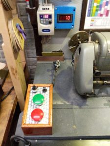
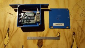
From there it was just a matter of building the box and wiring it up.
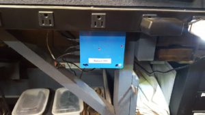
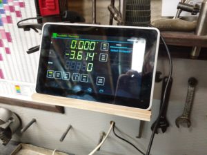
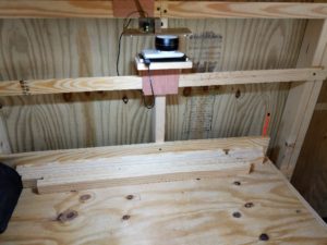
I’ve completed the software, built the circuitry on protoboard, packaged it up and installed it.
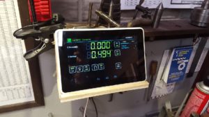
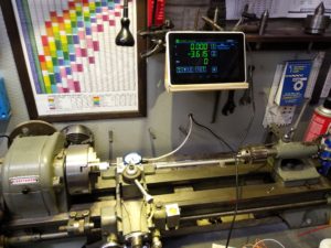
The software – since the Z axis used an iGaging scale and the X axis used a Harbor Freight caliper, I had to mash up two different Arudino sketches to deal with two different protocols, making sure that they did not fight. I used the iGaging TouchDRO sketch as the base. It managed the bluetooth interface to the tablet and the iGaging stuff. I replaced the iGaging code for the X-axis with the Harbor Freight code. The only issue is that the Harbor Freight code blocks if it is not receiving a data stream from the caliper, so both axes need to be hooked up for it to work. Initially the response from the iGaging side was slow – readout lagging, but once the circuit was properly soldered up that went away, and bluetooth reliability went up, so it was probably a noise problem when the circuit was on the plugboard.
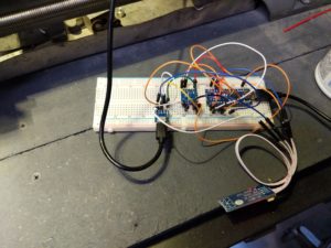
The circuit – I’m using a better quality protoboard, so building the circuit was pretty easy. First time I used surface mount resistors. 1206, about rice grain size. Easier to solder up than I expected.
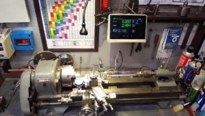
After that it was a matter of getting the circuit in a box and hooking stuff up. I had originally installed the X axis scale I(the caliper) on the tailstock side of the crossslide, but it was interfering with the chuck, so I moved it to the tailstock side. That required a fairly hinky linkage, with some backlash, so I should probably rebuild that some day.
I also had an iGaging setup for the Z (carriage) axis, pretty much out of the box.
So it turns out that several folks, most prominently Yuri has done a lot of work to make a Bluetooth adapter for iGaging (and other) DRO scales that interfaces with tablets, phones and so forth.
Yuri is selling adapters, but he has also developed and documented Arduino solutions that work with his TouchDRO app.
So I bought a cheap refurbished tablet, breadboarded up the Arduino circuit, and got the Z axis working!
Next steps:
See if I can get the TouchDRO tablet app working with the Harbor Freight X axis setup.
Create the Arduino code combining the X axis with the iGaging Z axis setup.


 w
w