A while back Big Clive published a video about controlling a string of LEDs with a PIC 8 pin microcontroller. I lost track of the video but I remembered the concept and thought I’d give it a try. It’s based on the fact the LEDs are diodes that conduct in one direction only, and that the GPIO pins on the chip are “tri-state” – think plus, minus and off. Given that you can control 6 LEDs with three wires, and 12 with four wires. The eight pin PICs have 5 input/output pins ( a sixth is input only) so we should be good to go. Here’s the chip, standard 8 pin DIP package.
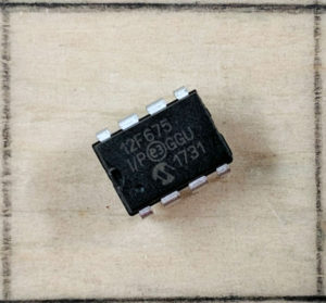
8 pin micro in a one inch square
Let’s say we want the three wire version. We solder the LEDs in one direction – wire 1 to 2, 2 to 3, 1 to three, and then do the same in the opposite direction for a total of six. Then we program the micro to switch the wires – 1 plus, 2 minus, 3 off lights the LED that is wired anode to 1 cathode to 2 for example.
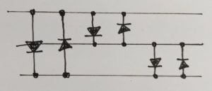
The pin states are not actually plus, minus and off. They are output logic high, output logic low, and input (high impedance). The output high = plus, and low = minus works fine, but high impedance on the input is not quite off, so you will get enough current leakage to light some LEDs that should be off unless you can choose your current limiting resistors just right.
Real programmers would write the code in assembler, but I chose to do it in C, just because I could. I used Matlab X and the PICkit 3 programmer. Getting the PICKit 3 to work is a drama that has been covered in many videos. Just plan to spend a few hours finding the secret sauce to make it all work. All you have to do is control two registers – TRISIO to define the state of the pins, and GPIO to switch them on and off when they are defined as output.
The heart of the code (for the three wire version seen in the cigar tube) looks like this:
#define _XTAL_FREQ 4000000
#define DELAYTIME 500
#define LED1 TRISIO=0b111100;GPIO=0b000101;
#define LED2 TRISIO=0b111100;GPIO=0b000010;
#define LED3 TRISIO=0b111001;GPIO=0b000011;
#define LED4 TRISIO=0b111001;GPIO=0b000100;
#define LED5 TRISIO=0b111010;GPIO=0b000001;
#define LED6 TRISIO=0b111010;GPIO=0b000110;
//////////////////////////////////////////////////////////////////////
// Start here
void main() {
int i;
init_ports();
ANSEL = 0b000000;
CMCON = 0b111111;
//OSCCAL=0x3468;
while (1) { // infinite loop
LED1
__delay_ms(DELAYTIME);
LED2
__delay_ms(DELAYTIME);
LED3
__delay_ms(DELAYTIME);
LED4
__delay_ms(DELAYTIME);
LED5
__delay_ms(DELAYTIME);
LED6
__delay_ms(DELAYTIME);
}
}
In the four wire version I used an array rather than DEFINEs to enumerate the LEDs. This allows you to use loops and so forth for the sequences, but it eats a good part of the 64 bytes of data memory on the little chip.
// LED array 2 dimensions – Switch (GPIO) and Mask (TRISIO)
// for 12 LEDs
const char Led[12][2] =
{
{0b000001,0b111100}
,{0b000010,0b111100}
,{0b000001,0b111010}
,{0b000100,0b111010}
,{0b000001,0b101110}
,{0b010000,0b101110}
,{0b000010,0b111001}
,{0b000100,0b111001}
,{0b000100,0b101011}
,{0b010000,0b101011}
,{0b000010,0b101101}
,{0b010000,0b101101}
};
/******************************************************************************/
/* Main Program */
/******************************************************************************/
//////////////////////////////////////////////////////////////////////
// Start here
// Four wire, 12 LEDs – GPIO 0,1,2,4
void main() {
init_ports();
ANSEL = 0b000000;
CMCON = 0b111111;
//OSCCAL=0x3468;
while (1) { // infinite loop
// bottom to top
for(int j=0;j<12;j++) { LedOn(j); __delay_ms(DELAYTIME); void LedOn(int i) { TRISIO = Led[i][1]; GPIO = Led[i][0]; } Next maybe I'll move on to a 12F1840 with four times the program memory and a bunch of built in peripherals.