Recently I’ve been working on a couple of upgrades to my old Craftsman (Atlas) 6 inch metal lathe. One thing I never bothered doing on the lathe was single point threading, because the lathe had manual change gears and I didn’t have a good enough reason to get into tearing down and setting up the gears for threading.
Recently I found a version of an Electronic Lead Screw from Youtuber “Clough42”. Rather than gears directly driving the lead screw at the appropriate ratio, the spindle speed (RPM) is read by a rotary encoder, a microprocessor computes the ratio for the lead screw and drives a stepper motor at the proper RPM. The computation has to consider the count resolution of the encoder, the step resolution of the stepper motor, and the speed of the leadscrew required for the desired feed. And it has to do it quickly, so a pretty powerful TI microprocessor is used. It reads the encoder in hardware, and is fast enough to compute the requirements every 5 microseconds. At the speeds I run, that means the processor will have checked on average 400 times before a change in position requiring some action happens. So I don’t think I’ll have any problem with accuracy.
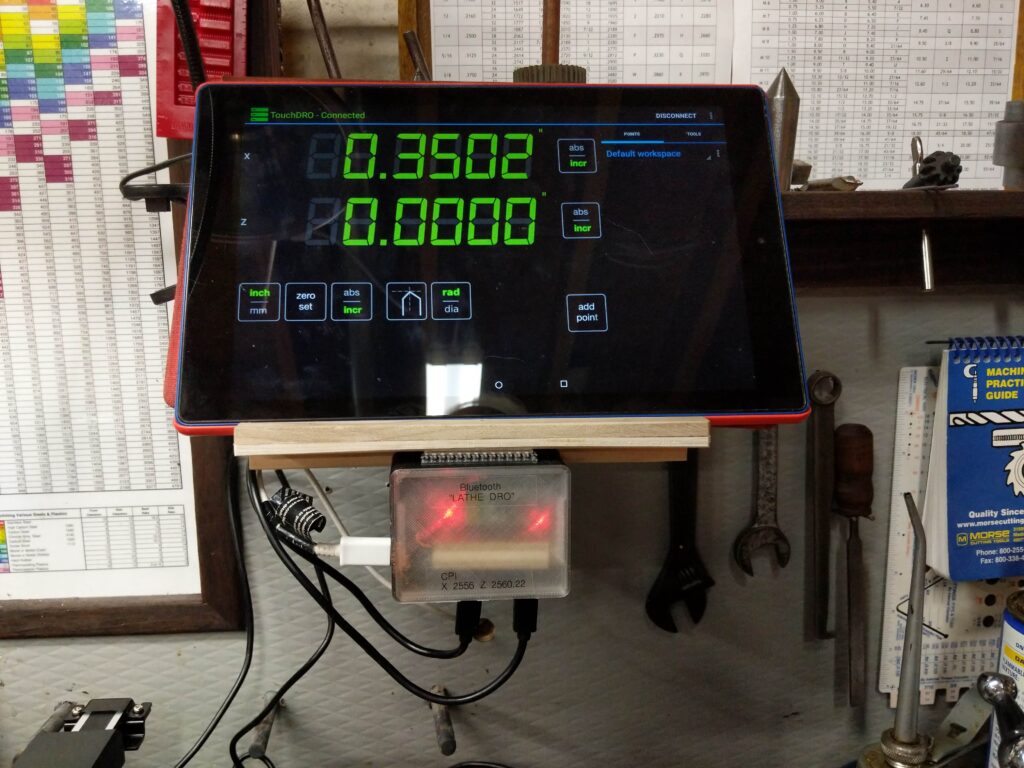
The other thing I did was to replace the Digital Readout that I had cobbled together some time ago. It was a hybrid that used an iGaging DRO for the Z axis and a Harbor Freight digital caliper for the X axis. The data from these are sent via Bluetooth to an app called TouchDRO running on a tablet. The original never worked well because the code reading the digital caliper was blocking, and when it failed or was absent, nothin worked. I decided to replace the caliper with another iGaging scale and interrupt driven software.
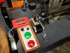
The Electronic Leadscrew
The details and links to many videos can be found at Clough42’s github.
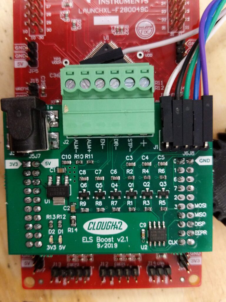
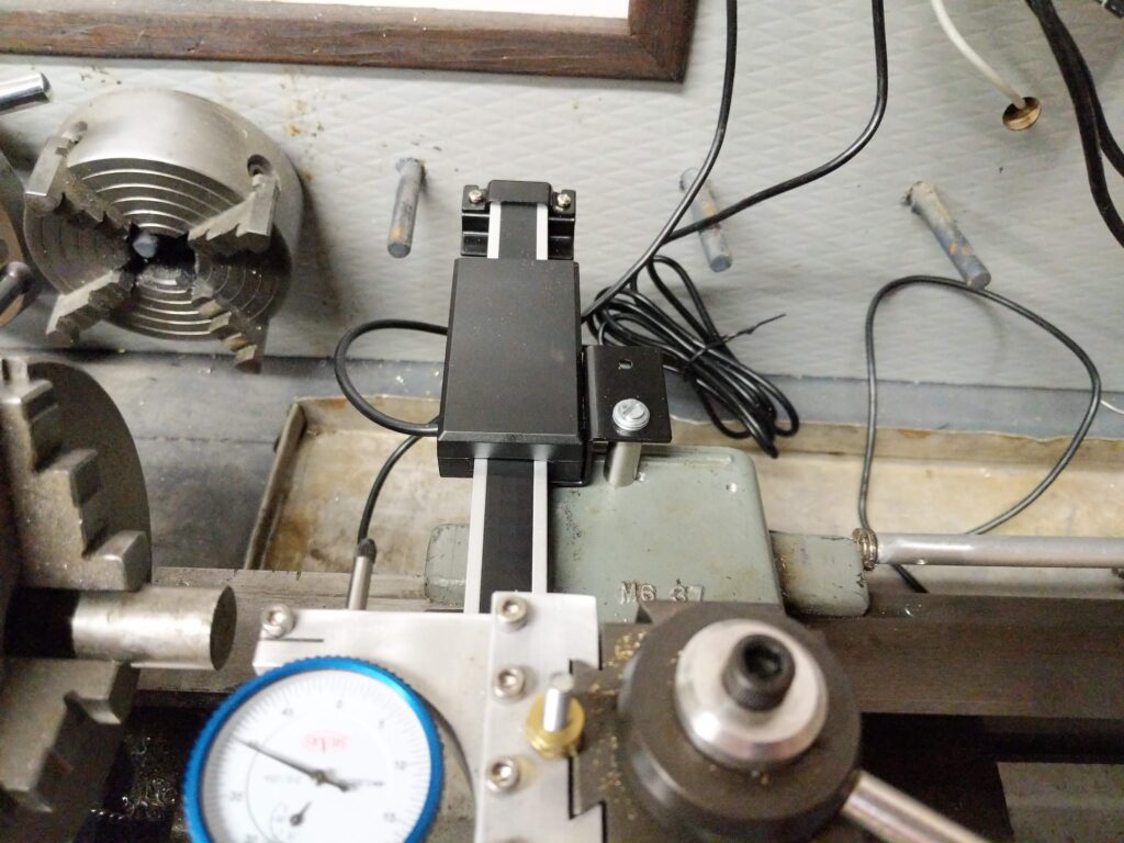
I bought an interface directly from him – on eBay. This links the microprocessor to the display and the stepper driver. The mechanical parts came mostly from AliExpress. I 3-D printed the display case and the microprocessor enclosure. Also machined a bracket for the encoder.
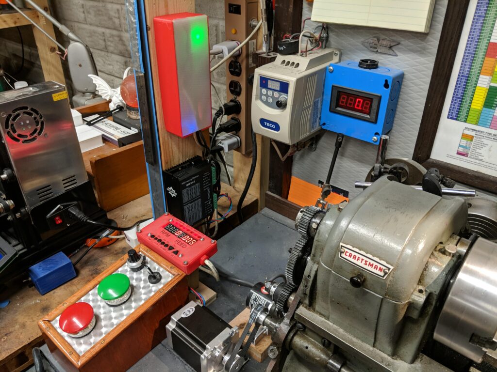
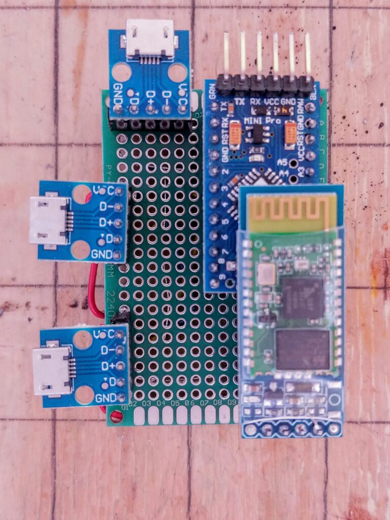
DRO
The DRO uses an Arduino Mini Pro and a Bluetooth Serial board. These connect to the iGaging scales via USB micro connectors. The scales are powered and clocked from the Arduino and return a position that is transmitted to the TouchDRO software via Bluetooth. The software has features for absolute and incremental positioning, radius vs diameter, and a bunch of other stuff for defining tools and so forth.