We are refurbishing on a 1/2 inch to the foot scale model of the Little Theater at Midland Center for the Arts (Midland, MI). I’m working on a stage lighting model. The basic components are:
3D printed lighting instruments with 5050 Neopixels
A lighting controller based around a Raspberry Pi Pico microcontroller
The functionality is:
Eight programmable channels ( possibly with multiple instruments)
In program mode, each channel can be adjusted for hue and brightness
In run mode, a master dimmer controls all the channels from black to maximum brightness for the channel
Presets and can be stored and recalled.
At this point I have eight instruments printed and assembled, and basic program and run mode working.
Next, I need more instruments and the programming for presets.
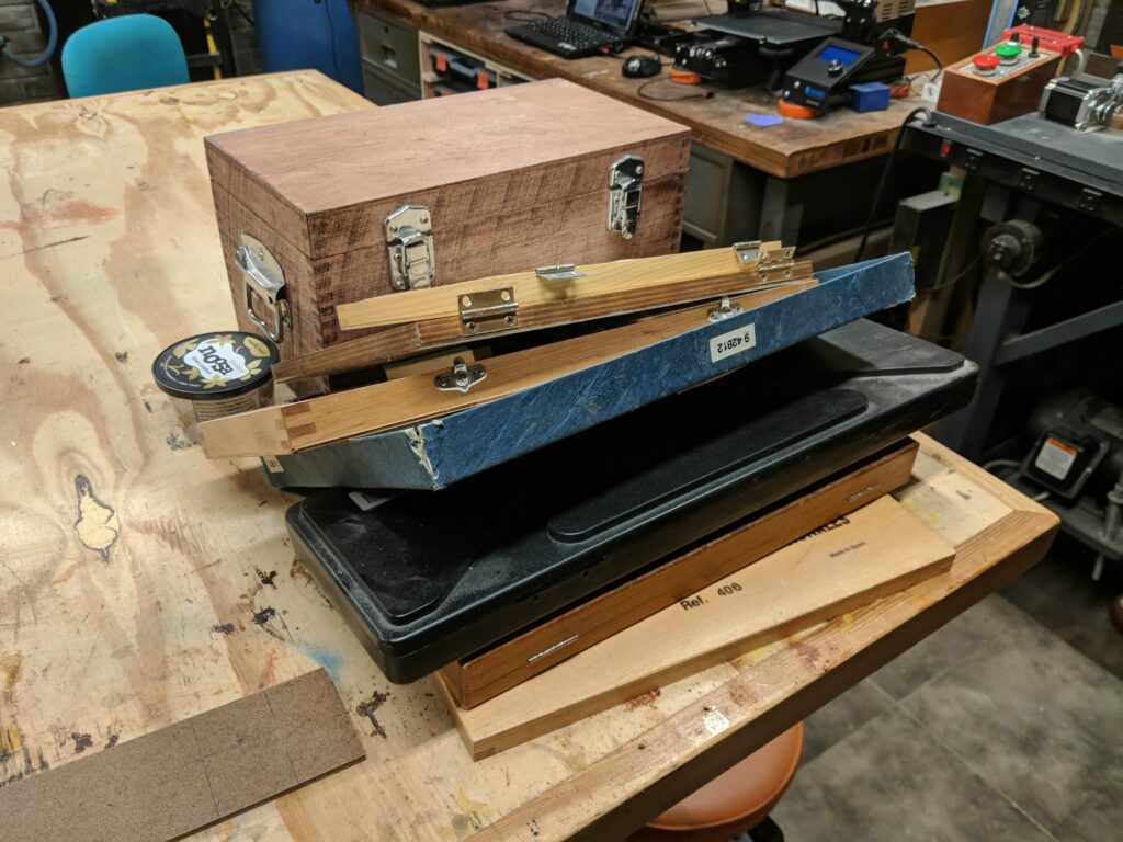
I don’t know about you, but as I buy more tools I end up with more boxes, containers and packaging .
Time to build a tool cabinet. Here are my design rules
Nicer than a plywood box but,
Not fine furniture
Use standard dimensional lumber (I don’t have a planer or jointer)
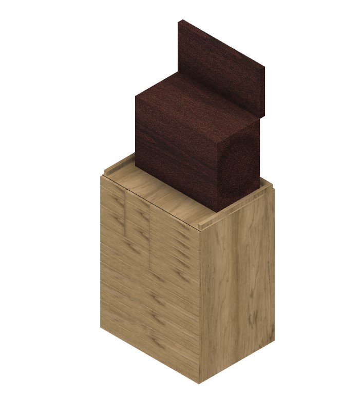
I did some initial work in Fusion 3d – not a full design, just some concept stuff.
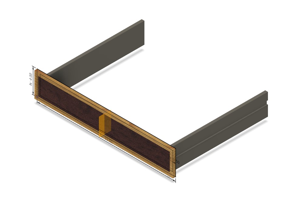
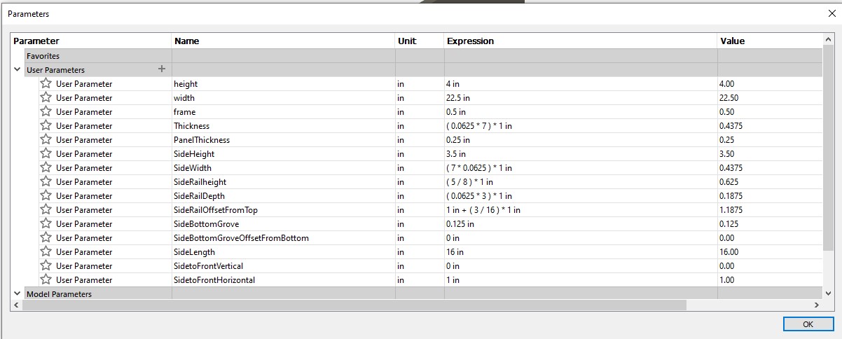
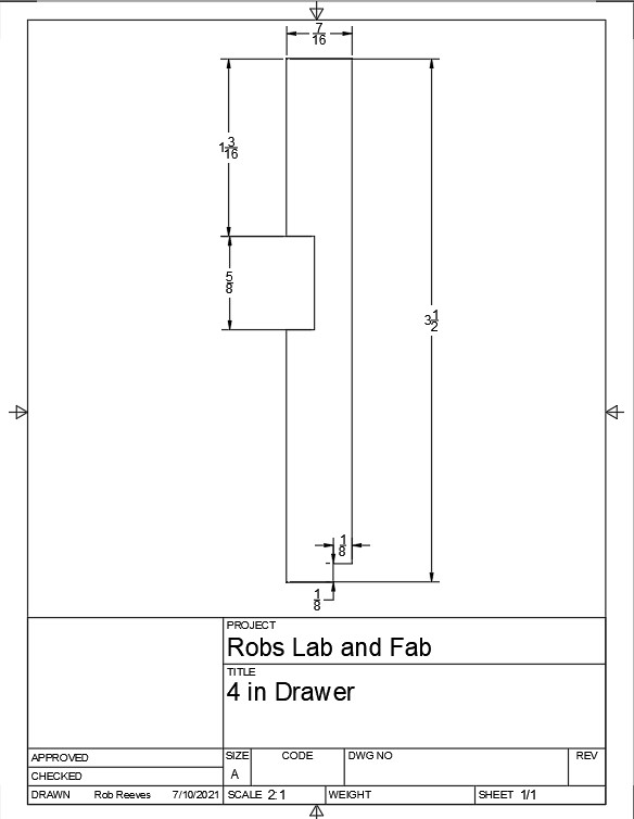
I did design a parametric drawer so that I could easily dimension the various sizes and positions
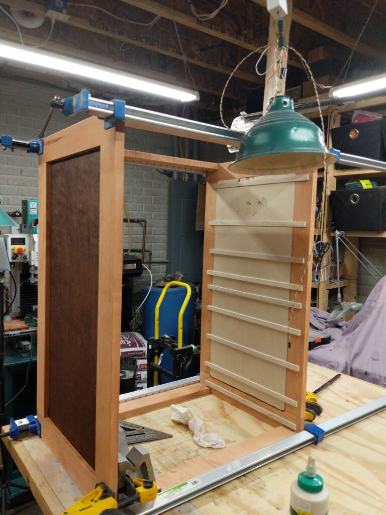
And on to construction
Here is what I learned:
Use gauge blocks – I laid out the drawer rails with a ruler. Worked fine on the sides, but the inner ones were harder and got slightly out of line. So lots of drawer adjustment was necessary.
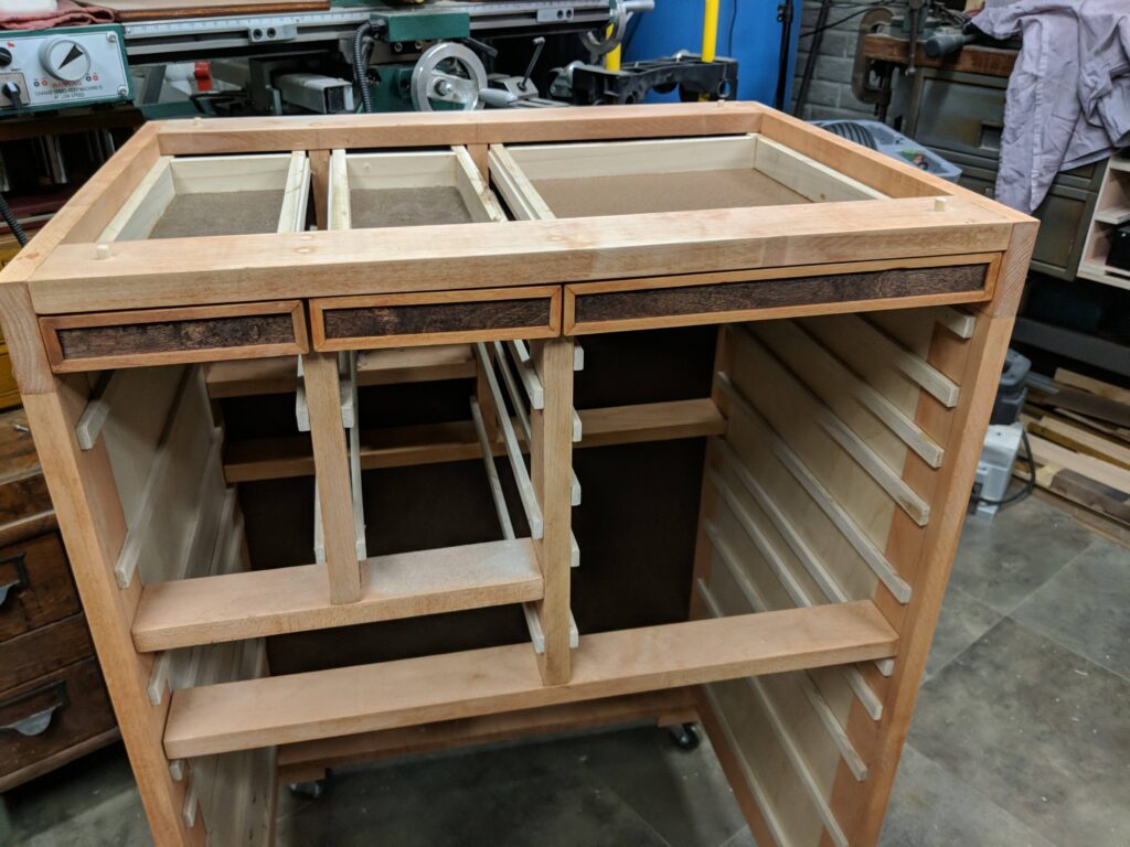
Grain – I thought I could get away with cheating on the direction of the birch plywood to save material – in line with my no fine furniture rule. So the bottom two drawers look a lot darker.
Don’t use standard dimensions. You can’t get two 24 inch pieces from a 48 inch piece. Should have cheated everything a bit smaller.
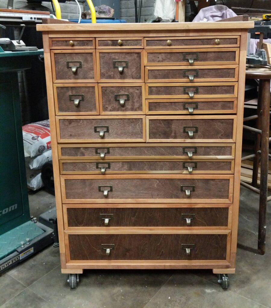
Still needs a bit of drawer orthodonture, but it soaked up a lot of tools and got rid of lots of stacked boxes
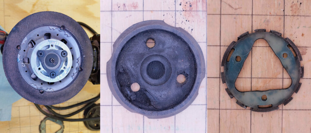
My friend Scott managed to blow up the inner disk of a rotary disc sander. The challenge is to replace it with a 3-D printed part. I’m guessing the probability of success is very low. A lot of effort went into shock mounting on the original, and a printed part will be brittle. Also it will be a thermoplastic, so it won’t tolerate a lot of friction heating.
Sander and original parts
The original soft material tore out. That was backed up by a fiberglass insert
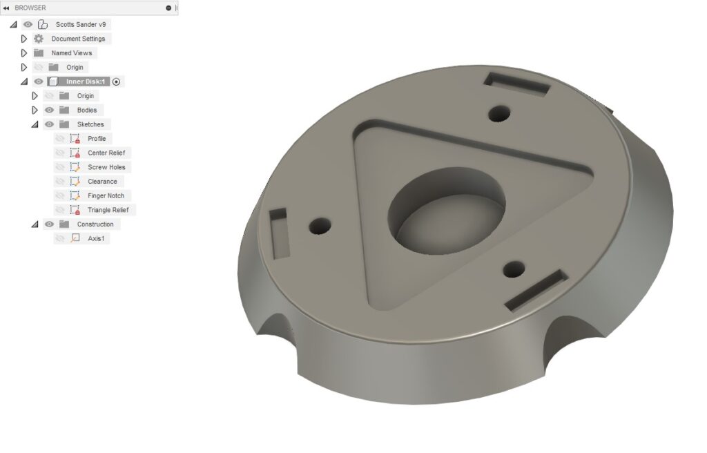
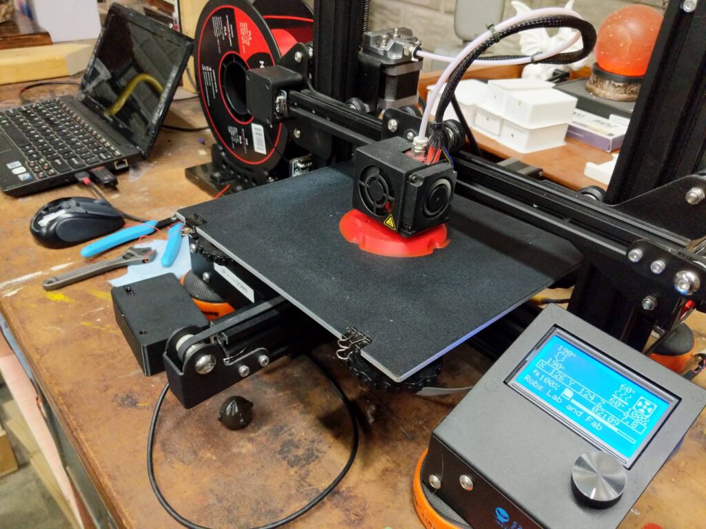
This is the new design in Fusion 360And here it is on the printer. Took about three tries to get the dimensions right. Scott has it on the sander and . . . so far, so good.
Need to see how it holds up on a real job. The good thing is that we can always make these by the batch!
Recently I’ve been working on a couple of upgrades to my old Craftsman (Atlas) 6 inch metal lathe. One thing I never bothered doing on the lathe was single point threading, because the lathe had manual change gears and I didn’t have a good enough reason to get into tearing down and setting up the gears for threading.
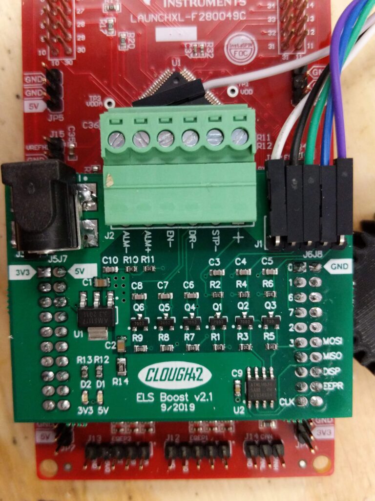
Recently I found a version of an Electronic Lead Screw from Youtuber “Clough42”. Rather than gears directly driving the lead screw at the appropriate ratio, the spindle speed (RPM) is read by a rotary encoder, a microprocessor computes the ratio for the lead screw and drives a stepper motor at the proper RPM. The computation has to consider the count resolution of the encoder, the step resolution of the stepper motor, and the speed of the leadscrew required for the desired feed. And it has to do it quickly, so a pretty powerful TI microprocessor is used. It reads the encoder in hardware, and is fast enough to compute the requirements every 5 microseconds. At the speeds I run, that means the processor will have checked on average 400 times before a change in position requiring some action happens. So I don’t think I’ll have any problem with accuracy.
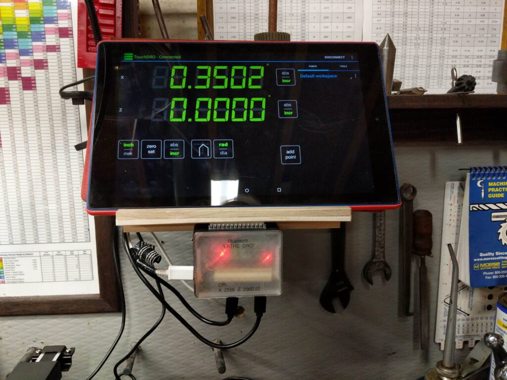
The other thing I did was to replace the Digital Readout that I had cobbled together some time ago. It was a hybrid that used an iGaging DRO for the Z axis and a Harbor Freight digital caliper for the X axis. The data from these are sent via Bluetooth to an app called TouchDRO running on a tablet. The original never worked well because the code reading the digital caliper was blocking, and when it failed or was absent, nothin worked. I decided to replace the caliper with another iGaging scale and interrupt driven software.
I bought an interface directly from him – on eBay. This links the microprocessor to the display and the stepper driver. The mechanical parts came mostly from AliExpress. I 3-D printed the display case and the microprocessor enclosure. Also machined a bracket for the encoder.
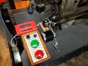
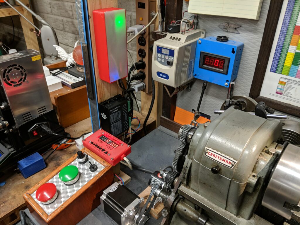
Directly above the lathe power controls is the Electronic Leadscrew control. The encoder is belt driven from a gear with a 1:1 ratio to the spindle The leadscrew is belt driven by the stepper motor. Off to the left a are the stepper controller (black box) and the stepper power supply (metal box below the controller)From this angle you can see the microprocessor mounted above the stepper controller. To the right of the processor enclosure are the VFD and the old tachometer for the lathe, which is now redundant to the RPM readout on the Leadscrew control panel
DRO
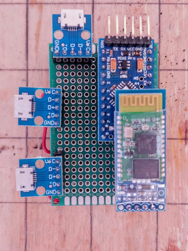
The DRO uses an Arduino Mini Pro and a Bluetooth Serial board. These connect to the iGaging scales via USB micro connectors. The scales are powered and clocked from the Arduino and return a position that is transmitted to the TouchDRO software via Bluetooth. The software has features for absolute and incremental positioning, radius vs diameter, and a bunch of other stuff for defining tools and so forth.
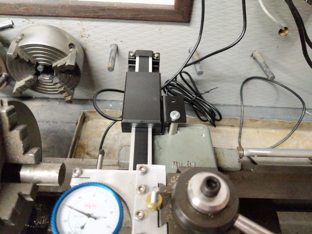
This is the controller consisting of the Arduino Mini, the Bluetooth module (HC-06) and usb micro sockets for power and the two scalesThe X-axis scale is mounted on the cross slide. Z-axis is behind the ways. Later I made a cover for the X scale to keep out chips and other grunge.And here it is using the Kindle as readout. The controller is in a 3-D printed case with a translucent cover so that we can see the indicator lights. Solid red on the right says Bluetooth is connected.
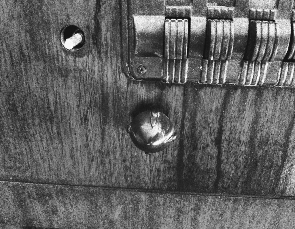
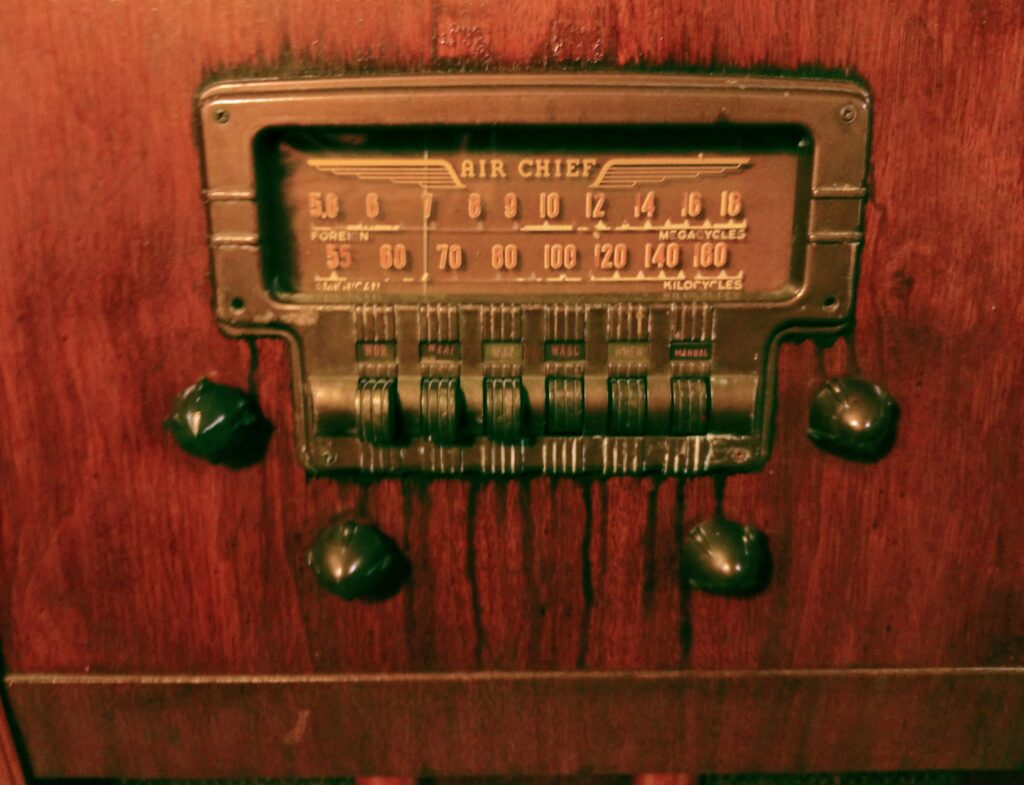
When we moved – four years ago – one of the knobs on my classic floor model radio was lost.
Time to fix it. Usually the way to do this is with a resin casting, but I don’t have the materials for that, and a hundred dollar investment in all the stuff I would need seems a bit excessive for one knob.
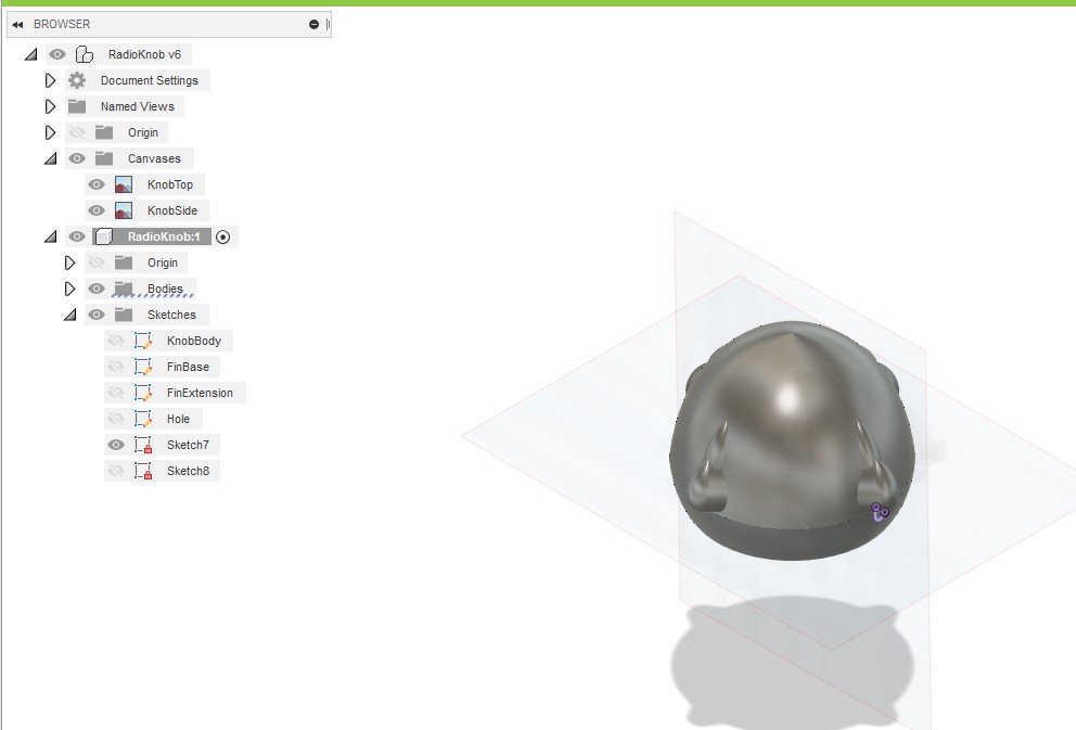
So, we’ll go the 3D printing route. First design in Fusion 350
I scaled a couple of photos, and then traced a spline which I rotated around the central axis. Then I modeled the “pips” the same way, with a partial rotation and circular repeat.
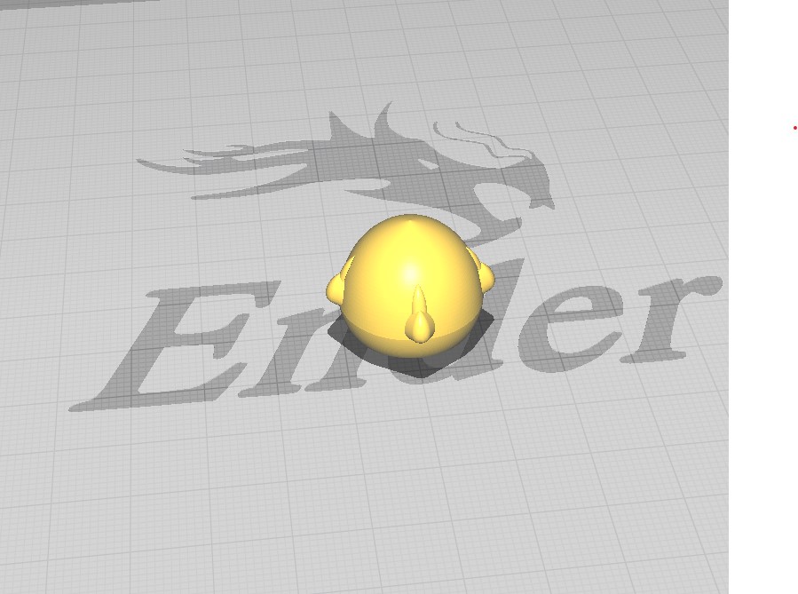
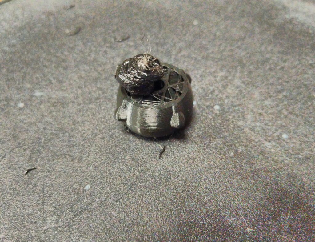
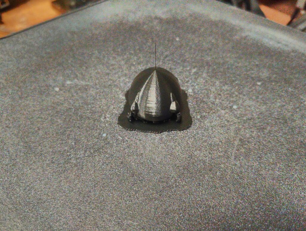
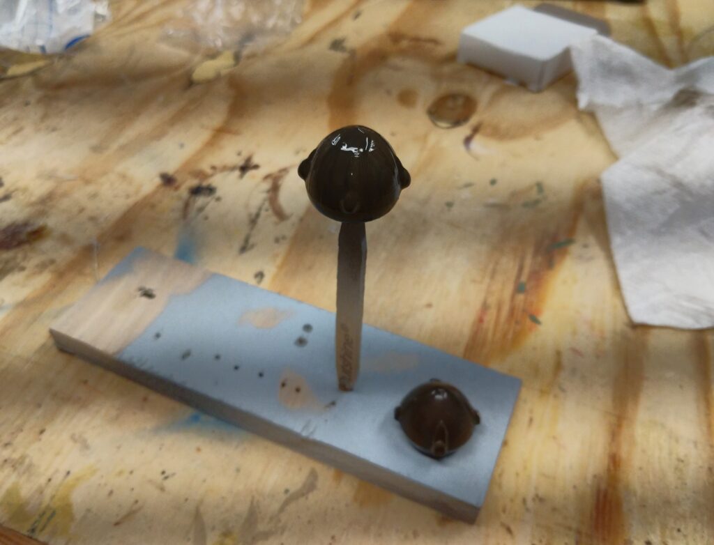
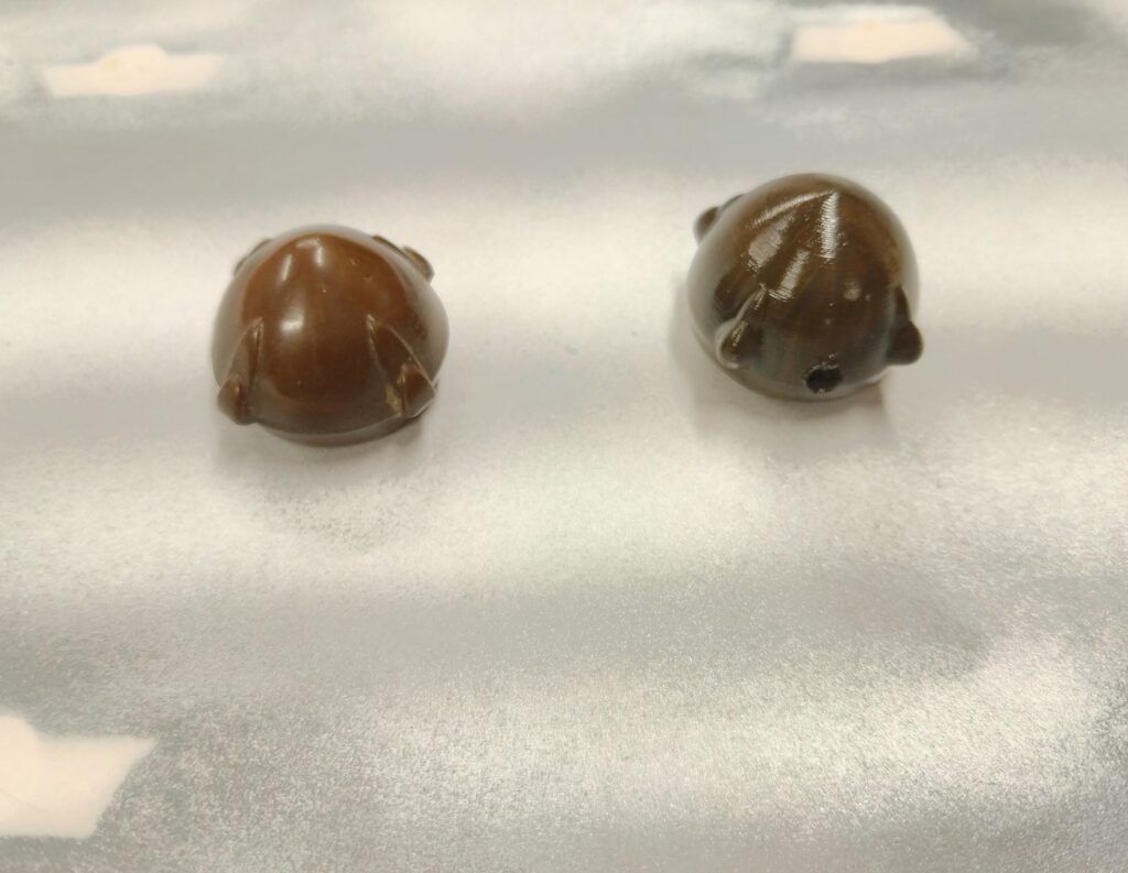
Slice in CuraAnd print – Oops, that didn’t go too well.BetterPaint to matchPretty close – a little dark maybeAnd done! Back in service
Well, not quite. There were a couple of things I did not like. The most important was that the set screw was not holding well because I printed the knob with 20% infill, and the screw only had a couple of threads to grab. So I reprinted it solid and added a flat bottom at the same time – and now it’s really done.
Besides the usual home and garden projects, here are some of the things I’ve been working on during the shutdown. I mark March 19th as the beginning of the shutdown for me – it was my last day in the Midland Center for the Arts Scene Shop. I was alone that day, working on the set for “A Gentlemen’s Guide to Love and Murder”. Of course, the show has not gone up, and there is no indication when we will restart.
DMX
Since I can’t be in the theater, I decided it was time to teach myself about DMX – the protocol used for most stage lighting and effects. I sort of missed the transition from manual and proprietary lighting systems to the standardization around DMX. It’s a pretty simple protocol that repeatedly sends a packet of up to 512 bytes over an RS-485 network. Each receiver knows which of the 512 channels it is assigned to, and interprets the value of the it’s bytes into some action. For example, a dimmer would be assigned one channel and would interpret value (0-255) as a brightness level. A spotlight might have many channels controlling colors, pan and tilt motors, and effects wheels. No error correction – if a message is missed the receiver just keeps doing what it was and waits for the next time – which will be in about a 30th of a second.
I read up on the protocol and decided to build some devices using Arduino class micro-controllers. I ended up building a little 48 channel lighting desk and using some receivers from eBay. I also built a receiver using an Arduino Nano that could be programmed to control Neopixels, for example.
3-D Printed Instruments
Solar Fountain
Collin’s 3-d printed cheetah lives in my little solar fountain. I decided to print some other critters so that the cheetah had some company.
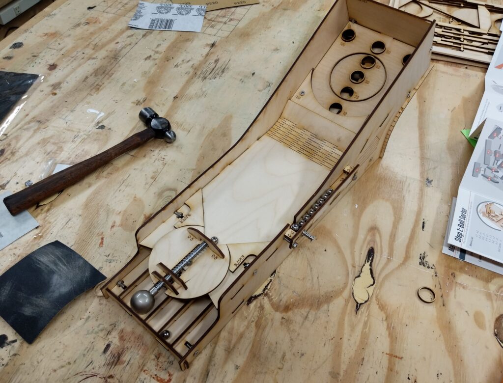
Ski Ball
Father’s Day gift from Beth, Ben and the kiddos. A very well made laser cut wooden kit. Fun to assemble, and it has a nice smoky smell too. I need to machine a little bushing to guide the shooter. It’s riding in two holes in the wood now, and it tends to bind up a bit.
Retropie
I couldn’t resist buying a Raspberry Pi 4, and then I had to figure out what to do with it. Running from a SSD Drive instead of an SD card has become popular because it is more reliable and much faster. Native support for this just came out for the Pi 4, but I was a little early, so I used Berryboot – which initially boots from SD and then reboots from a choice of images on the SSD drive. I currently run Nighthawk – which is a Windows 10 look alike (still actually Linux) and Retropie. Retropie emulates many of the 80s and 90s game machines, so if you can get the code for the games you can play Nintendo, Sega, etc, etc games using the Raspberry Pi. Nintendo 64 is about as current as it gets, and there are complaints about performance. With the exception of some sound issues that I have yet to work out, it runs fine for me on the Pi 4
Instrument Cases
3-d printing projects to make cases for Sonoff devices and some electronics toys – Open Bench Logic Sniffer and Bus Pirate.
Annunciator
I -finally- got around to fixing the display on the annunciator and got it mounted above the door in the shop. 3-d printed a plate for the control panel and mounted the display. Also designed and printed holders for the keyboard and the remote for the display.
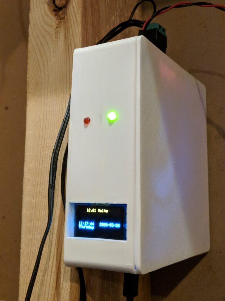
Installed and working. I designed and printed the case.
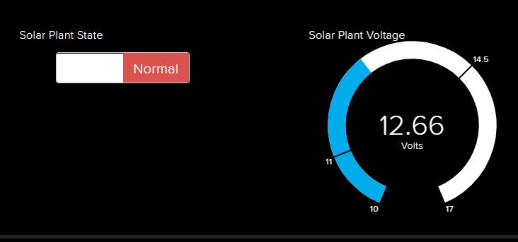
Installed and started monitoring via Adafruit IO
I have a few software enhancements in mind. Ability to turn the boost charger on from the web for example.
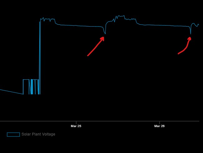
Also there is a strange phenomenon happening each morning. The voltage goes low enough to trigger the boost charger. I wonder if this is happens when the solar controller first turns on. Maybe I need to set the threshold a bit lower.
It’s been cloudy enough this winter that the solar plant charging has not been able to keep up with demand. Short days and new consuming devices contribute to the problem. I have had to use a trickle charger to keep up.
I’d like to automate this process so that the back-up charger comes on when the panels can’t keep up. When the battery voltage drops below a certain level, the charger should take over.
Here is what I spec’d out.
/*
Solar Monitor – RHR March 2020
Monitor voltage on solar installation and initiate back up charging
when voltage drops below 11 volts.
ESP8266 microprocessor so it can talk to the interwebs
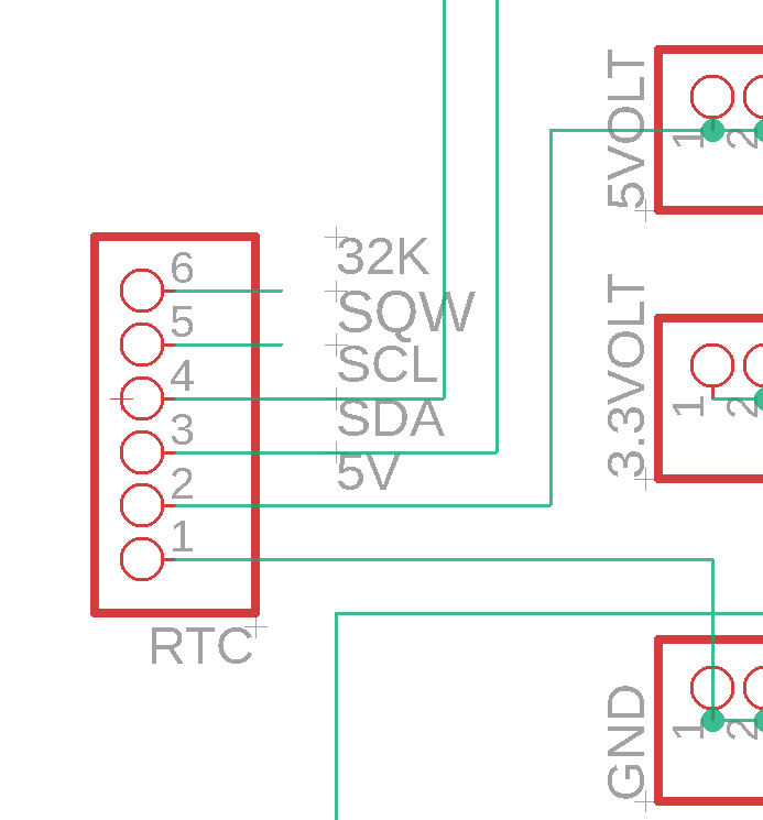
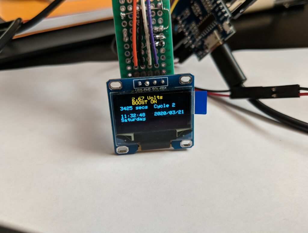
Real Time Clock to time operations OLED to display parameters Measure voltage on AO (analog to digital line) via 5 to 1 voltage divider Report to Adafruit IO
IF voltage falls below 11 volts, turn on trickle charger for one hour
Turn off and check voltage
If below 12 turn charger back on.
*/
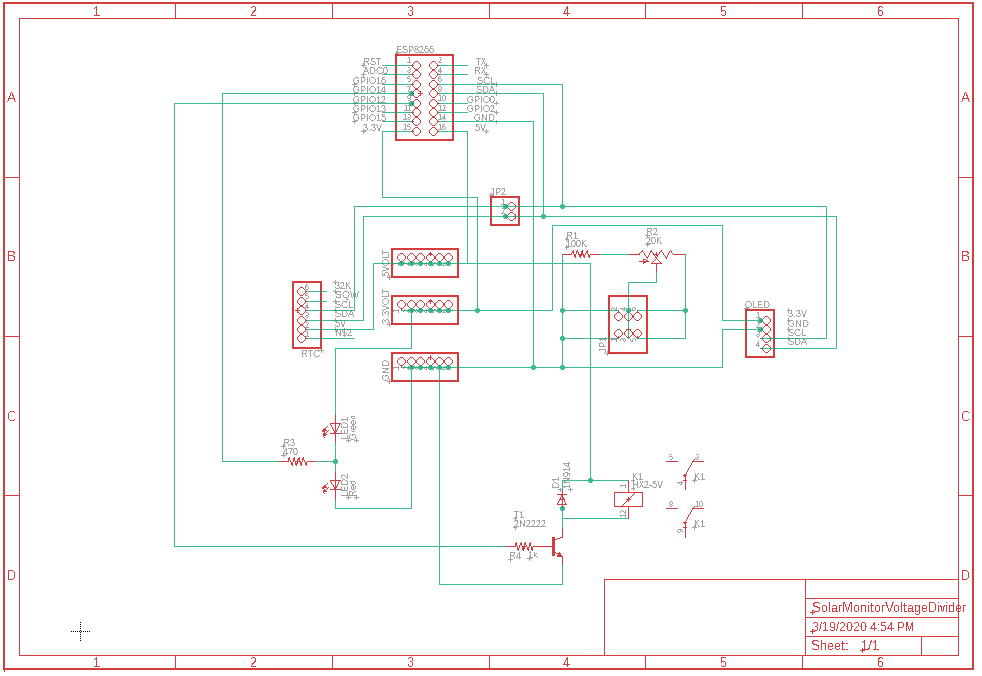
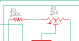
The schematic looks like this.The voltage divider maps the charger range (up to 17 volts) to the ESP8266 ADC range (about 3 volts)
The Real Time Clock measures the charging time and any other timing requirements.
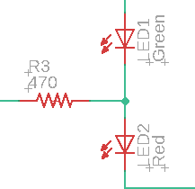
These LEDs indicate that the back up charger is active (red) or off (green)
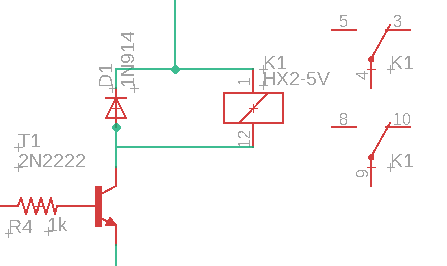
and this relay actually controls the trickle charger.
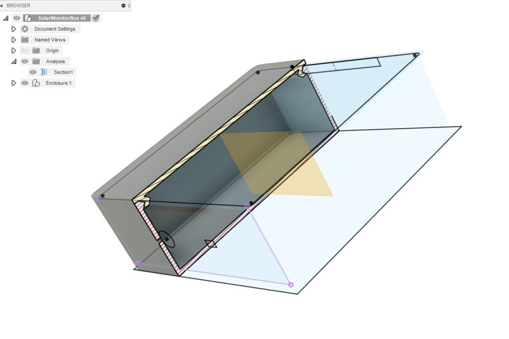
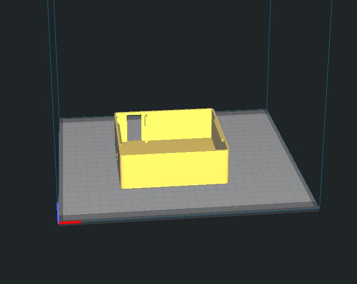
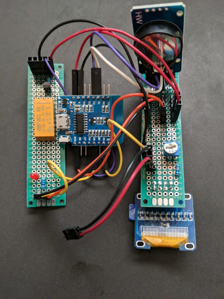
The circuitry is kind of all over the place. From left to right: Proto board with relay and indicator LEDs, the ESP8266, protoboard with Real Time Clock, display and voltage divider. I’ll have to 3d print a case to stuff all this in.It’s verking!
Next steps – add the IOT software to talk to the internet, actually wire in the trickle charger, and then come up with a case.
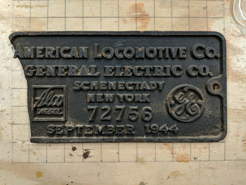
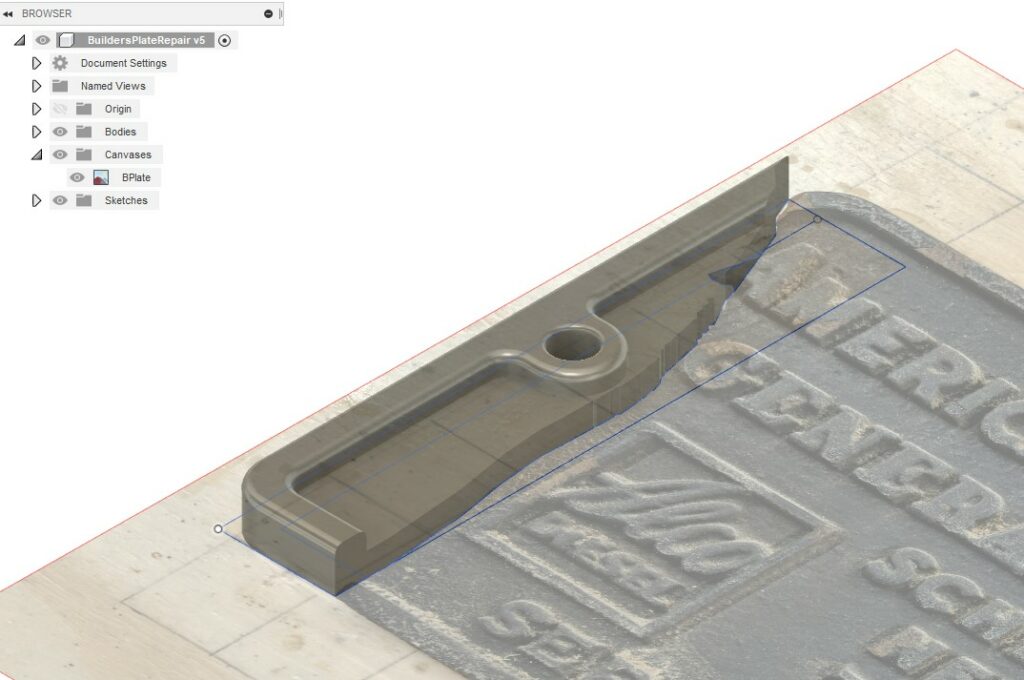
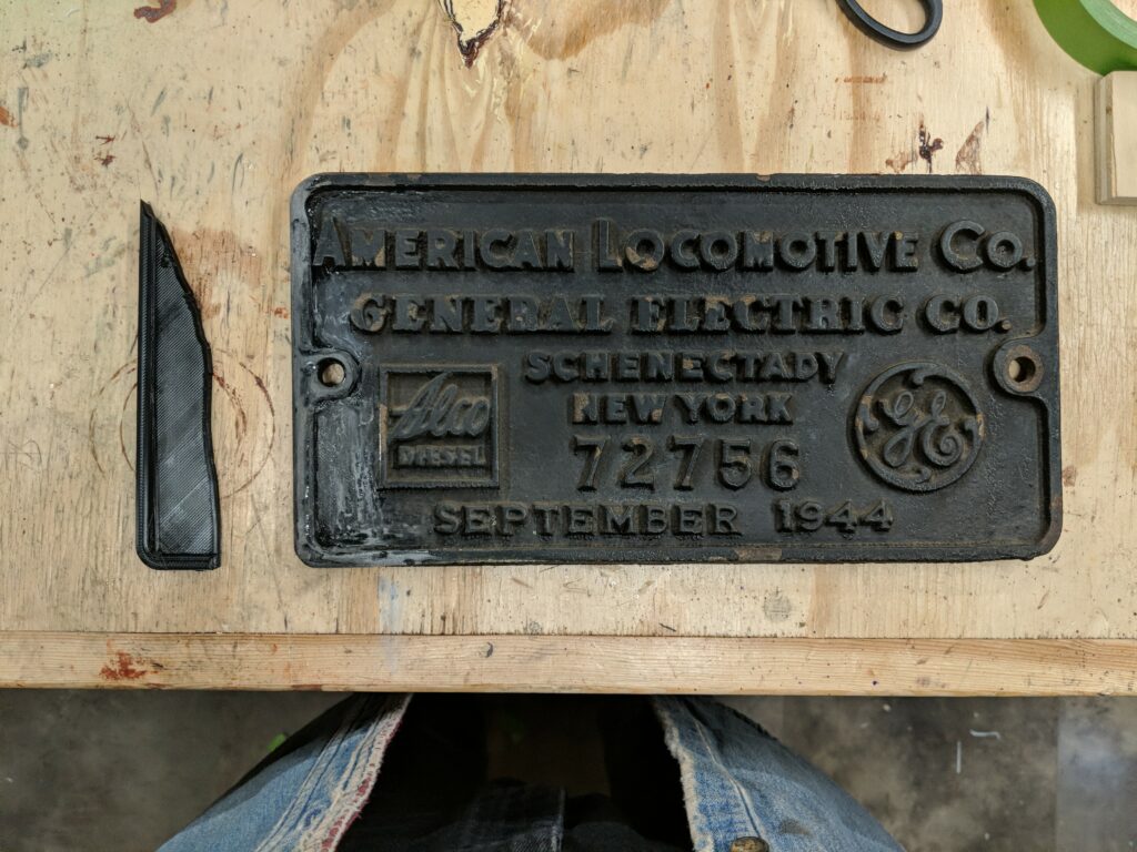
In my youth I ‘ahem’ obtained a locomotive builder’s plate from the locomotive graveyard in the Fair Haven yards of the New Haven Railroad. It had a corner broken off, so I never did anything with it other than haul it around for fifty years.
I got to thinking that maybe 3d printing offered a way to repair it. But first I looked up some of the history. It looks like this may be the last loco of it’s class delivered to the New Haven railroad in 1944.
619 Alco S-2 DEY-5 9/1944 72756
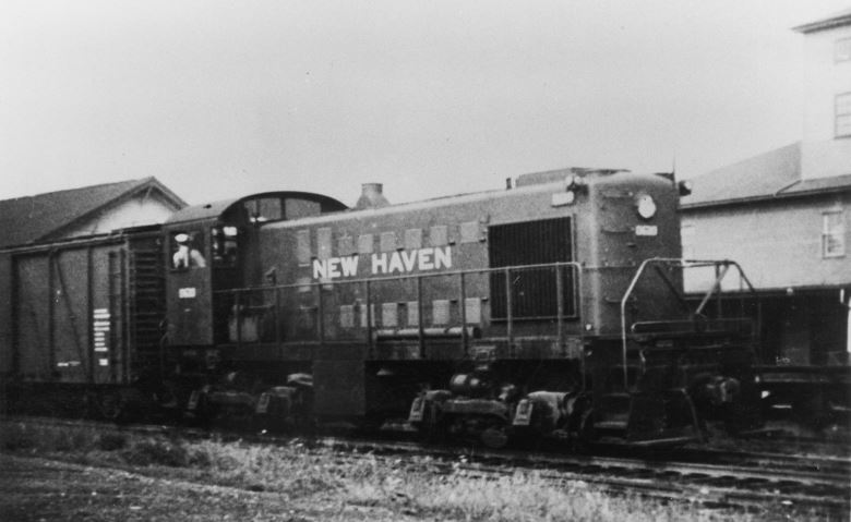
DEY-5 – Alco S-2 A turbo-charged version of the S-1, they were also used in both yard duty and on local freights. Like the DEY-3s, the cab was slightly shorter and ‘flatter’ than the Alco standard for clearance in the electric zone.
At some point in 1944 (during the second and final New Haven deliveries) Alco changed from horizontal side radiator louvers to vertical louvers as on their other switchers and road switchers. New Haven locomotives #0600-0608 had horizontal side radiator louvers.
Paint Schemes
Delivery: The then-standard switcher scheme of Pullman Green with Dulux Gold lettering and black frame.
Late ’40s Scheme: Hunter Green Cab with Warm Orange on the back of the cab and the entire hood except a small Hunter Green fillet on bottom of hood at the cab. Black underframe. Warm Orange script herald on cab.
A little design work in Fusion 360 to repair the corner
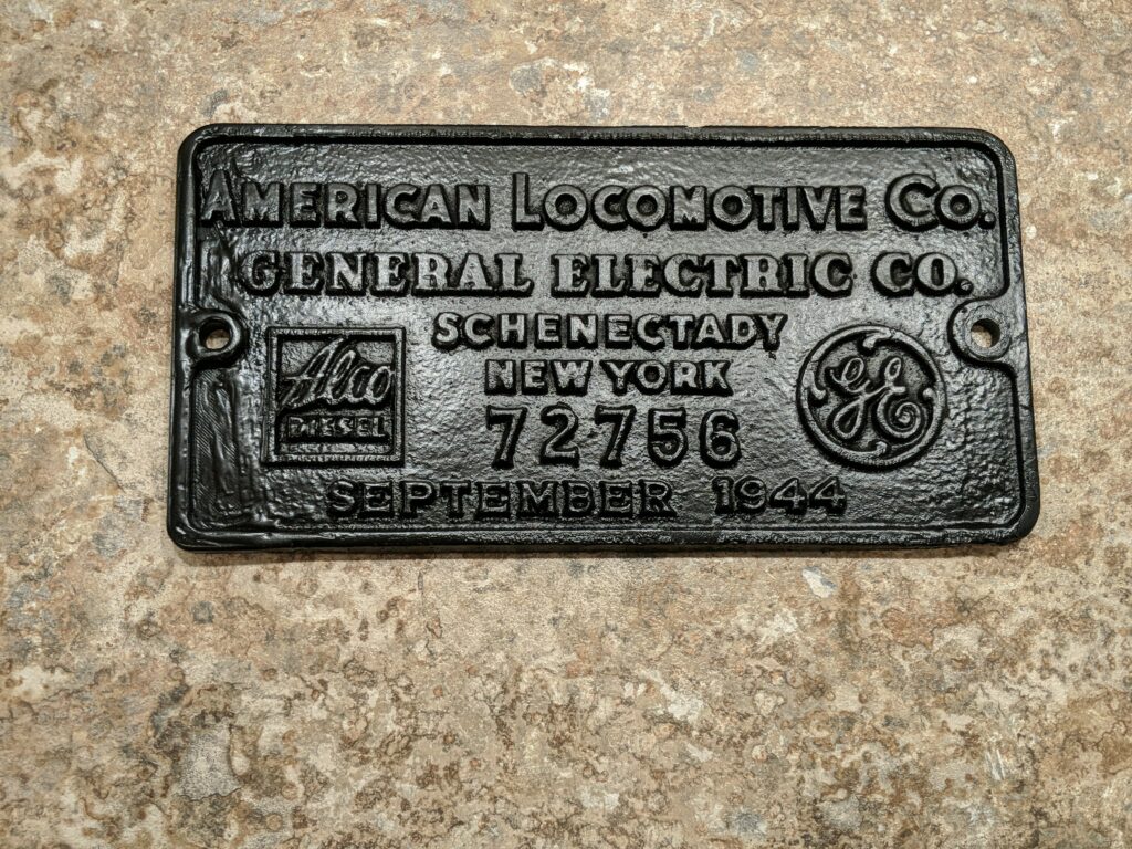
I designed the repair in Fusion 360, blended it in with some epoxy resin, and painted flat black. It’s presentable now.
I got a few ESP microcontrollers – ESP32 and ESP8266. These are Arduino type micros with Wi-Fi and (optionally) Bluetooth built in. The ESP8266 is actually the basis for the Sonoff controllers.
This means you can control the micro from the internet, and by extension the Amazon Echo or Google Assistant. I chose Adafruit IO as the service broker – more about that later.
I had built a little fixture to use as a macro photography stand. I wanted a way to light the subject which led to the following:
Build something to control a ring of intelligent LEDs – Neopixels
Control this from the internet – use Adafruit IO to control the brightness, color, and number of pixels lit.
Use IFTTT to interface Alexa and Google assistant to Adafruit IO.
So now I can control the light ring from a PC, tablet or phone. Or by talking to it.
Then I came across a color sensing device. This “looks” at a surface and derives an RGB color value for what it “sees”
OK, now imagine I can look at a color and tell my neopixel ring to mimic it.
Build a device to read the sensor and tell me what it “sees”
If I see a color I like, send it to Adafruit IO, where it in turn can control the Neopixel ring, or any other arrangement of Neopixels I care to play with.
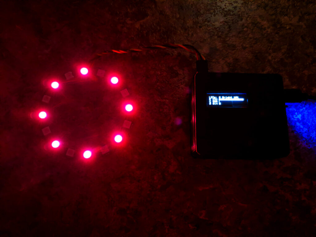
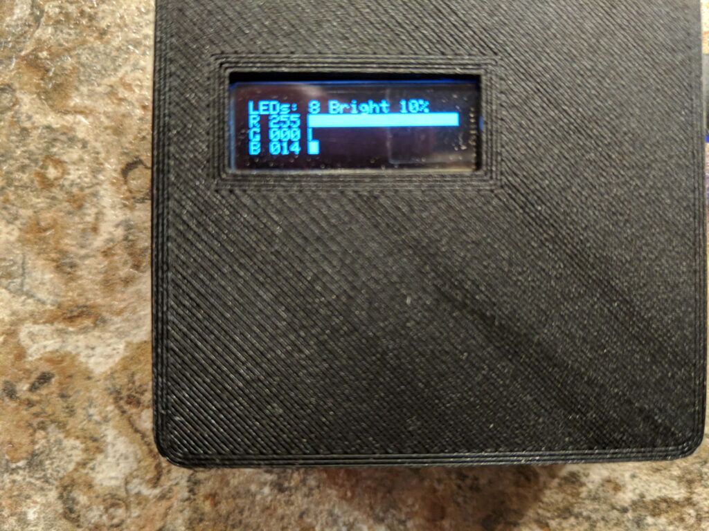
This is the Neopixel controller. This one controls a ring of sixteen LEDs. you can select brightness, number of leds, and the color. Your choices are shown on a small OLED display.
Number of LEDs lit, the brightness percentage, and the color values (0 – 255) and bar graph.
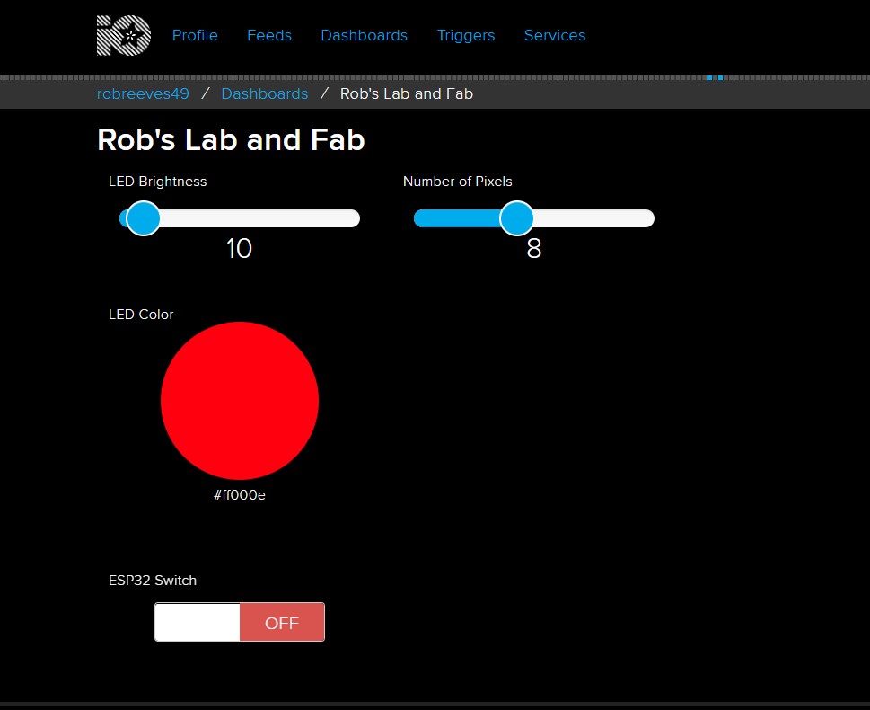
Here is the Adafruit IO “dashboard” that controls the thing. You are allowed up to 10 “feeds” that can send and receive data to and from a web connected device. It acts as an MQTT broker, which accepts data “published” to a feed, and sends data to devices that “subscribe” to the feed. Essentially, both your Adafruit IO and your device “listen” for stuff that is for them (based on your subscription authorization and feed names and so forth) then act accordingly.
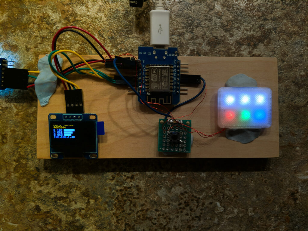
And this is the color sensor bread-boarded up. The three top LEDs show the color sensed, and the lower three are the individual Red, Green, Blue intensities. The OLED display is similar to the one on the controller – showing the color values. Pushing the button “publishes” the color value to the Adafruit IO dashboard, where the controller can pick it up. So you can scan a color and set the LEDs you are controlling to it.
Of course you can also manipulate the dashboard from any internet connected device.
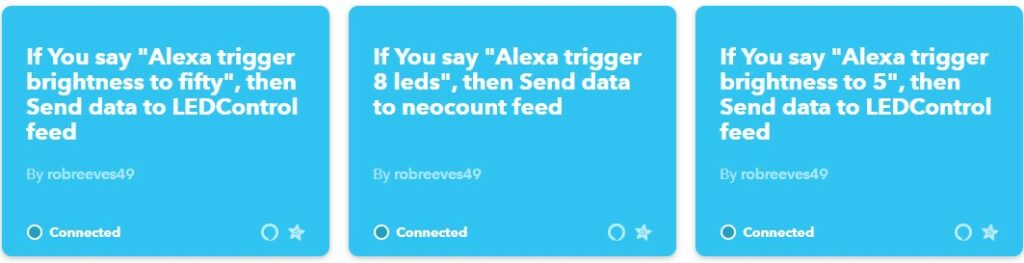
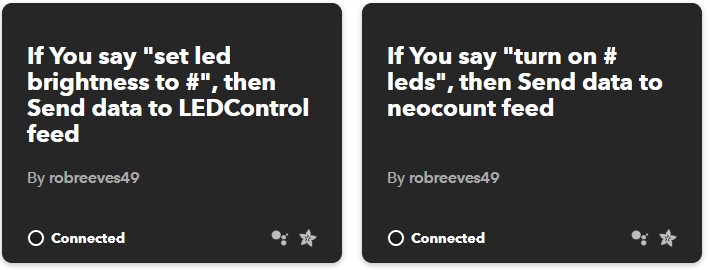
Finally, there is voice control via IFTTT
This part got a bit tedious because the commands have to be set up individually. Google Assistant is a little smarter – it understands numbers and so forth so it took setting up only three or four commands instead of a unique one for every action
So that’s where I am on this one. I can see controlling any sort of deck or display lighting by extending these prototypes.